NOTICE: The Processors Wiki will End-of-Life on January 15, 2021. It is recommended to download any files or other content you may need that are hosted on processors.wiki.ti.com. The site is now set to read only.
The default Flash Loader Project implementation downloads firmware updates over asynchronous serial and stores them into an external serial flash. After the image has been successfully downloaded and validated the MCU is reset at which point the Flash Loader Bootloader runs. The bootloader will detect the new firmware image in the external SPI.
Bluetooth Low Energy Wiki Main Page
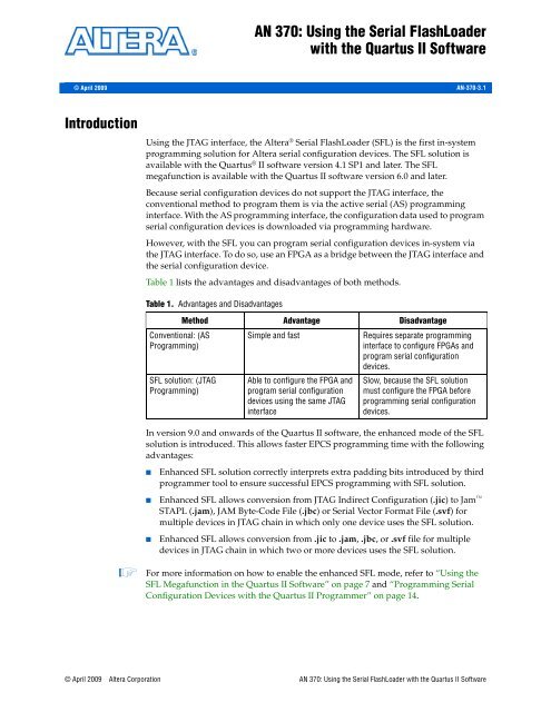
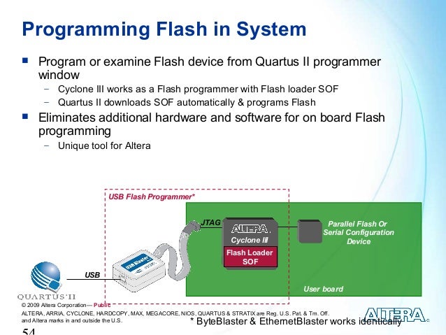
- Jrunner + Serial Flash Loader (SFL) + EPCS4 How to programm EPCS without Quartus II Hello, I'd like to adapt Jrunner to work with Serial Flash Loader. I've integrated SFL megafunction into my design and it works great. When I click auto detect in quartus II programmer it detects Cyclone II.
- FPGA Serial Flash Loader IP core is an in-system programming (ISP) solution for Intel FPGA serial configuration devices. In-system programming offers you the option to program your serial configuration devices using a JTAG interface.
- 1Serial Bootloading
- 10Encrypted Bootloading
Serial Bootloading[edit]
This example explains the Serial Bootloader (SBL) and provides a step-by-step procedure of how to compile a project for the SBL and load it into the CC254x's flash. This document will also describe how to use an encrypted version of the SBL - the EBL or encrypted bootloader. Note that there is also an example SBL-configured project included with the 1.4.0 stack release - HostTestRelease.
Serial bootloading is a feature that enables a cc254x device to load into flash an embedded software image from a host processor through a serial interface such as UART or SPI. This demo consists of a CC254x target image which is compiledas an SBL-enabled configuration, a CC254x programmed with the SBL, and the CC254X_SBL_Tool which will function as the host. The SBL code resides at the bottom of the flash memory in the CC254x, as shown below.
Guaranteed to work with all Intel intellectual property (IP) blocks, such as the serial flash loader or ASMI parallel IP blocks Designed for maximum efficiency Offer in-system programmability (ISP) and reprogramming capabilities not available with one-time-programmable devices The Intel FPGA configuration devices have the following advantages. The serial flash loader is a small piece of code that allows programming of the flash without the need for a debugger interface. Two serial interfaces are supported for download to the device, UART and SSI. The serial flash loader uses a packet type interface to provide reliable.
Upon power cycle, a decision is made in the SBL whether to start serial boot loading or to jump to the downloaded image area. This decision is made based on the validity of the downloaded image. If the image in the downloaded image area isnot a valid image, the serial boot loader starts in serial boot loading mode and waits for commands from host processor (the PC in our case). If the image in the downloaded image area is valid, the boot loader jumps to the valid image area. The host processor is the intelligent part of the protocol: it chooses the image sector to download, reads back the downloaded image area sector to verify the written image was written correctly, and authorizes the use of the image, etc.
Image Validation[edit]
For each image, the CRC is calculated at build-time and placed at the beginning of the SBL target image as defined by the linker configuration file (cc254x_f256_sbl.xcl), as shown below:

Immediately following the CRC in flash is a CRC-Shadow which is computed in the SBL after an SBL of the image completes to determine if the download was successful / the image is now valid.
Requirements[edit]
- 1 SmartRF05 kit with CC254x Evaluation Module
- Texas Instruments Stack 1.4.0 which can be downloaded from www.ti.com/blestack
- Serial cable to connect from computer to SmartRF (possibly USB-to-Serial)
Project Files[edit]
The SBL IAR project can be found in C:Texas InstrumentsBLE-CC254x-1.3.2ProjectsbleutilSBL.
The EBL IAR project can be found in C:Texas InstrumentsBLE-CC254x-1.3.2ProjectsbleutilEBL.
Tools[edit]
The Serial Boot Tool (v.1.3.2) PC application can be found here
Source code for the Serial Boot Tool (v.1.3.2) PC application can be found here
Compiling a Project for Use with the SBL[edit]
The following steps allow you to load a file using the SBL. We will use the CC2541 SimpleBLEPeripheral application as an example. This project is located at: C:Texas InstrumentsBLE-CC254x-1.4.0ProjectsblesimpleBLEPeripheralCC2541DB. It will be loaded via UART to a SmartRF05 board with a CC254x EM. There is also a SBL configuration for a SPI bootloader included in the stack but that is out of the scope of this document.
1. Create a new project configuration for the SBL target image: Project->Edit Configurations->New. Call it CC2541-SBL and choose to base it on the CC2541 configuration.
2. In the compiler preprocessor options, add the following defined symbols:
- MAKE_CRC_SHDW
- FEATURE_SBL
- OAD_KEEP_NV_PAGES
This last definition (OAD_KEEP_NV_PAGES) is optional. If defined, the NV pages (non-volatile memory where bonding information, among other things, is stored) on the target device will not be overwritten. This will allow any previously bonded devices to remain bonded. If not defined, the NV pages will be overwritten and bonded devices will be forgotten.
3. Change the following linking options under the config tab:
- change the linker config file to: cc254x_f256_sbl.xcl
- add to the search path: $PROJ_DIR$....commoncc2540
Note: Some projects might already have this included or have different directory for the common folder($PROJ_DIR$........commoncc2540)
4. Change the following options under the extra output tab:
- change the output file to: application.sim
- change the output format to: simple-code
5. Under Build Actions, add the post-processor .bat file which will convert the .sim to a .bin for serial bootloading. Note that the file path and project name will be different as you work on different projects. Note that the last file name in this command must match the output file specified in step 5 (application in this example). Also ensure that there is exactly one space between each argument enclosed by quotations.
- '$PROJ_DIR$....commoncc2540cc254x_ubl_pp.bat' '$PROJ_DIR$' 'ProdUBL' '$PROJ_DIR$CC2541-SBLExeapplication'
Note again to double check the 'common' folder directory. If you are experiencing Java erors, it is likely due to incorrect path / file names.
6. Rebuild all. This will produce a .bin file in $PROJ_DIR$CC2541-SBLExe. This is the file you will serially load.
7. Load the SBL project onto a SmartRF+EM and run it.
8. Open the SBDemo application (see the Tools Section Above) and choose the .bin file created in step 6. Select the correct COM port with the following and choose 'Load Image.'
9. The PC application will write the image and then verify that it was written successfully by reading it back. The device will then reboot into the SBL, realize that it has a valid image, and jump to the target image.
Returning to the SBL[edit]
If, at any point during execution of the serially loaded image, you want to return to the SBL to load another image, you must call the appForceBoot() command which is defined in the sbl_app.c file. This can be done via
Serial Flash Loader
Note that, for the HostTestRelease project's sample SBL/EBL configurations, this is exposed via the HCI interface by using the HCI command UTIL_FORCE_BOOT (opcode 0xfe83).
Upon success, the device will reset to enter the SBL so there will be no Event returned. Otherwise, upon failure, the device will return the HCI Ext Command Status Event with the Status parameter set to 0x02 (INVALID_PARAMETER). See the TI HCI Vendor Specific API guide included with the installer for more information.
However, the simpleBLEPeripheral project (and most other projects) do not expose the HCI interface so another method (such as an interrupt, over-the-air message, etc) must be used to call the appForceBoot() command.
Generating a .hex of the SBL plus your Target Image.
[edit]
This section will describe how to flash the device so that it contains the SBL followed in flash by a valid target image. The idea is that the target image will run initially, then when it needs to be updated, we will return to the SBL as described above and load a new image. The easiest way to do this is to perform a serial load of your target image to the bootloader as described above, then read back the the entire .hex file (SBL + target image). This can be accomplished using Flash Programmer with the following settings:
Serial Bootloading Commands
[edit]
Serial boot loading command packets follow the same format as regular network processor interface commands. However, they are not exactly the same as serial boot loading commands are accepted only by the serial boot loader in serial boot loading mode and the underlying transport mechanism could be different from the one used by network processor image. For instance, the serial boot loader might be running at a 9600bps baud rate while network processor interface could be running at a 115200bps baud rate.
The serial boot loading communication is always triggered by the host processor followed by the the serial boot loader sending a response. Each command is described below. The SubSys byte in these commands denotes that the command is an SBL command. In the SBL, the 5 least significant bits are extracted and must be equal to 0xD (SBL subsystem). The SOF byte is 0xFE. The Len byte corresponds to the payload length (does not include the SubSys and CMD bytes). The last byte in each command is always the FCS which must match the FCS calculated by the bootloader. The FCS should be an XOR of the SubSys byte, CMD byte, and payload bytes.

- Handshake Command
Handshake is command ID 0x04. The handshake has no parameters. The handshake is sent by the host processor to determine if the boot loader is running target device.
Handshake Command:
| 1 Byte | 1 Byte | 1 Byte | 1 Byte | 1 Byte |
| SOF | Len | SubSys | CMD (0x04) | FCS |
The boot loader responds with a 1 byte status code indicating success (0x00).
Handshake Response:
| 1 Byte | 1 Byte | 1 Byte | 1 Byte | 1 Byte | 1 Byte |
| SOF | Len | SubSys | CMD (0x84) | Status (0) | FCS |
- Write Command
The Write command is command ID 0x01. The write is sent by host processor to write a page of flash to the bootloader. The write command has the following parameters:
Write Command:
| 1 Byte | 1 Byte | 1 Byte | 1 Byte | 2 Bytes | 64 Bytes | 1 Byte |
| SOF | Len | SubSys | CMD (0x01) | Address | Data | FCS |
The address contains a word aligned address of the image. The boot loader must add the base address of the program area to the address. The network processor boot loader responds to the write command with the status of the operation.
Write Response:
| 1 Byte | 1 Byte | 1 Byte | 1 Byte | 1 Byte | 1 Byte |
| SOF | Len | SubSys | CMD (0x81) | Status | FCS |
- Read Command
The Read command is command ID 0x02. The read command is sent by the host processor to read a page of flash from bootloader. The read command has the following parameters:
Read Command:
| 1 Byte | 1 Byte | 1 Byte | 1 Byte | 2 Bytes | 1 Byte |
| SOF | Len | SubSys | CMD (0x02) | Address | FCS |
The address contains a word aligned address of the image. The boot loader must add the base address of the network processor program area to the address. The bootloader responds to the read command with the status of the operation, the address, and the data.
Write Response:

| 1 Byte | 1 Byte | 1 Byte | 1 Byte | 1 Byte | 2 Bytes | 64 Bytes | 1 Byte |
| SOF | Len | SubSys | CMD (0x82) | Status | Address | Data | FCS |
- Enable Command
The Enable command is command ID 0x03. The enable command is sent by the host processor to indicate the image on the bootloader is valid. ***Note that the responsibility lies with the host processor to validate the image by reading it back and verifying. When the boot loader has received the enable command, it enables the downloaded code by writing the CRC to the CRC shadow and resetting the device. On reset, the bootloader sees that the CRC and CRC shadow match and jumps to the application.
Enable Command:
| 1 Byte | 1 Byte | 1 Byte | 1 Byte | 1 Byte |
| SOF | Len | SubSys | CMD (0x03) | FCS |
The boot loader responds with a 1 byte status code.
Enable Response:
| 1 Byte | 1 Byte | 1 Byte | 1 Byte | 1 Byte | 1 Byte |
| SOF | Len | SubSys | CMD (0x83) | Status | FCS |
Boot Loading Sequences
[edit]
The following two figures illustrate boot loading sequences and application image downloading sequences performed during boot loading. Note that the validity of the image is determined by checking the preamble (specifically CRC + CRC Shadow) of the application image area, which is updated only as the last transaction of image download sequence. If anything goes wrong during download of the image, such as power failure, the preamble of the image area is not updated and the SBL stays in boot loading mode waiting for boot loading command from host processor. When the image is valid, the boot loader jumps to the image area. Note that host processor reads back the application image to verify before enabling the image. The idea is to validate the written image without having to impose CRC checking in the serial boot loader. This was done to minimize the code size of the SBL. However, this increases the time taken for serial downloading since the entire image has to be read back.
Initial application image download sequenceConsequent Application Image Download Sequence
Encrypted Bootloading[edit]
This section will describe how to modify a project to use the encrypted bootloader (EBL) so that it will be impossible to sniff the UART/SPI lines to read the target image during a serial bootload. This is accomplished by using the AES-128 engine to encrypt the target image. Then, during a bootload, the EBL will decrypt the target image and place the unencrypted image in flash. Note that the HostTestRelease project provided with the installer includes an already created EBL configuration. It is assumed that you have already followed the above steps to create the CC2541-SBL configuration because the EBL configuration will be based on the SBL configuration.
Generating Unencrypted EBL Target Image[edit]
First, you must create the unencrypted EBL target configuration.
Quartus Serial Flash Loader Device Is Missing
1. In IAR, select Project->Edit Configuration. Select 'New...' and create a new configuration 'CC2541-EBL' choosing to base it on the 'CC2541-SBL' configuration (created as described above).
2. In the preprocessor definitions, remove 'FEATURE_SBL' and add 'FEATURE_EBL'

3. Also remove the MAKE_CRC_SHDW preprocessor define
4. In the Linker Options, under the 'Config' tab, select the linker file to be: cc254x_f256_ebl.xcl
5. In the Build Actions tab, under post-build command line, modify the command to be:
- '$PROJ_DIR$....commoncc2540cc254x_ubl_pp.bat' '$PROJ_DIR$' 'ProdUBL' '$PROJ_DIR$CC2541-EBLExeapplication'
Note that the relative path will contain different names as you work with projects other than the CC2541 SimpleBLEPeripheral.
6. Add the following compiler directive at the line following the appForceBoot() function in sbl_app.c (line 114):
7. Compile the project. The post-processing actions will produce an unencrypted EBL binary target image.
Encrypting EBL Target Image[edit]
Next, you must sign and encrypt this image for use with the EBL. In order to do this, we must modify the EBL project so that it will temporarily function as an 'encrypter'. To do this, open the EBL project from $INSTALLProjectsbleutilEBLiarcc254x. and:
1. Add the following preprocessor definitions:
- SBL_SECURE=FALSE
- SBL_SIGNER
2. If desired, modify the key used for encryption by modifying the aesKey structure in sbl_exec.c.
3. Compile the project and load it on a SmartRF05+EM with a serial cable attached.
Now we must serially load the unencrypted image to the EBL functioning as an encrypter in order to allow the EBL encrypter to encrypt the image and then read it back. To do this...
1. Open the Serial Boot Tool (see the Tools section above), select the unencrypted EBL target image, the correct COM port, use the following settings, and choose 'Load Image:'
2. Once the image has finished loading onto the EBL encryprer, select 'Encrypt Image' in the Serial Boot Tool. You may want to rename the 'Image Filename' in order to prevent overwriting the original unencrypted image. The Serial Boot Tool will then start reading back the encrypted EBL target image:
3. Once the encryption is complete, the encrypted EBL target image is now placed in your PC's file system.
Altera Serial Flash Loader Ip
Loading the EBL and Encrypted Target Image[edit]
Now that you have the encrypted target image, you can flash the EBL (functioning now as an EBL; not an encrypter) to the target device and then serially load the encrypted target image produced from the last step. To revert the EBL project back to EBL mode (and not encrypter mode):
1. Remove the following preprocessor define:
- SBL_SIGNER

and modify the following preprocessor define to be:
- SBL_SECURE=TRUE
2. Ensure that the aesKey matches the key from the previous section.
3. Lock the flash pages so that they can not be read back.
4. Compile the project and flash it on a SmartRF05+EM with a serial cable attached.
Adobe Flash Loader
Now, you can serially load the encrypted target image from the previous section using the Serial Boot Tool. As it is loaded, the EBL will unencrypt it and write it to flash. Furthermore, since the flash pages are locked for reading, the image will remain secure.
Further Considerations[edit]
See the previously mentioned sections for instructions to jump back into the EBL and to read the superhex (EBL + encrypted target image) from the target device.
You will need to implement some type of safe application-level mechanism to jump back to the EBL when it is desired to load another image. Otherwise, an attacker could force a jump to the EBL and use the bootloader Read Command to read back the unencrypted flash. Note that this functionality was discussed in the aforementioned 'Returning to the SBL' section when discussing the appForceBoot() command. The API is the same for the EBL.
{{
Please post only comments related to the article SerialBootLoader here. | Keystone=
Please post only comments related to the article SerialBootLoader here. | C2000=For technical support on the C2000 please post your questions on The C2000 Forum. Please post only comments about the article SerialBootLoader here. | DaVinci=For technical support on DaVincoplease post your questions on The DaVinci Forum. Please post only comments about the article SerialBootLoader here. | MSP430=For technical support on MSP430 please post your questions on The MSP430 Forum. Please post only comments about the article SerialBootLoader here. | OMAP35x=For technical support on OMAP please post your questions on The OMAP Forum. Please post only comments about the article SerialBootLoader here. | OMAPL1=For technical support on OMAP please post your questions on The OMAP Forum. Please post only comments about the article SerialBootLoader here. | MAVRK=For technical support on MAVRK please post your questions on The MAVRK Toolbox Forum. Please post only comments about the article SerialBootLoader here. | For technical support please post your questions at http://e2e.ti.com. Please post only comments about the article SerialBootLoader here. }} |
| Links | |||
|
